Creating Images for .nmd Files with Structure Information in VMD
You can make gorgeous images and gifs with the NMD structure information in VMD.
- Load in the NMD and structure, then align as described previously.
- Change the arrow color in the top right of the NMD Wizard pane. Trying to change it from the graphics menu will not work.
- Use the NMD Wizard Pane to modify the arrow settings. Some solid choices are
Arrow cylinder radius: 0.1andArrow/porcupine cone radius: 0.4. - Change the
Graphics materialto your choosing. If you want the default Hard Plastic, you may need to deselect it and reselect it to make the changes take effect! - After modifying the arrows, then modify the graphic display. If you go back
to the arrows later, you may need to redo your specifications for the
default_name coordinatesstructure…
Important: If you are highlighting a residue, make sure
that that residue is not being colored by another command! It will NOT render
properly, and you’ll be upset that it wasn’t colored as intended.
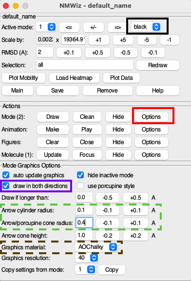
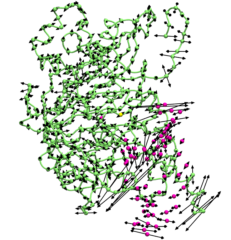
Table: Graphical Representation of 1: default_name coordinates
| Style | Color | Selection | Modified Property | Material |
|---|---|---|---|---|
| Tube | ColorID 12 | all | Radius: 0.2 | AOChalky |
| VDW | ColorID 12 | name CA and not resid 251 | Sphere Scale: 0.4 | AOChalky |
| VDW | ColorID 4 | name CA and resid 251 | Sphere Scale: 0.4 | AOChalky |
| VDW | Color 28 | name P C2 “C4’” | Sphere Scale: 0.4 | AOChalky |